
The Box

I built a box. More specifically it's a LED light box that responds to music.
It was fully inspired by this box from Anamanaguchi's Endless Fantasy video.
I wanted to build the box at some point in 2014 but I didn't get around to it until this summer. I started in July and didn't fully "finish" it until late October.
The Parts
The Box Itself
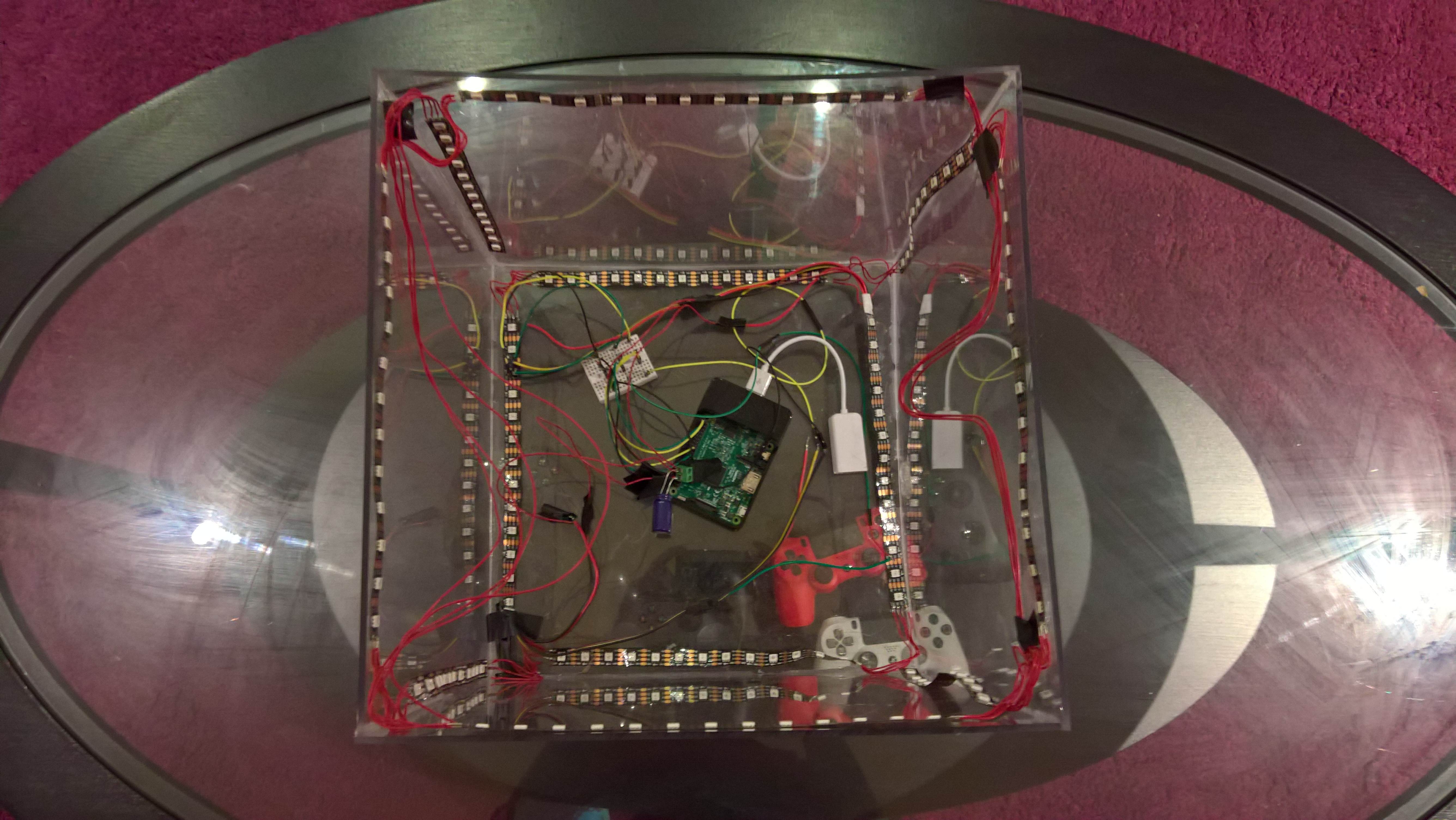
The box is 12 inches cubed. The sides are acrylic glass (Plexiglass) and I shoddily stuck it together using acrylic cement. I also bought an acrylic glass cutter tool so I could make a hole for wires. That really didn't work as planned. After attempting to cut a hole in the already glued together box for half an hour, I just used my soldering tool to melt a hole in the box.
It worked but I do not recommend you do this.
The LEDs
I first started looking at LEDs on Adafruit. It was confusing at first because they sell branded versions of LED strips. This can give you a pretty good idea on how many different types of LEDs there are. I wanted a LED strip where I could control the color of each LED on the strip individually. Those type of strips are called RGB addressable strips (some other types here). LED strips also have different requirements when it comes to clock timings and power needs. Since I initially started looking at the LED strips sold by Adafruit I was trying to decide between LPD8806s, NeoPixels, and DotStars since those three were RGB addressable. Now ignore the last two names I just mentioned, Adafruit's NeoPixels are actually WS2812Bs and DotStars are APA102s. After reading more about the differences I learned that the LPD8806s and the WS2812Bs are somewhat specific about their timing requirements. APA102s on the other hand don't have specific timing requirements. This means I had more options on what board I could use to drive the LEDs. So I ended up getting 4 meters of APA102s with 60 LEDs per meter on AliExpress. Since an edge of the box would be 12 inches I could probably get up to 18 LEDs on an edge. I decided to put 13 LEDs on an edge to account for any shenanigans that could happen. The LEDs were $12.78 per meter on AliExpress instead of $29.95 on Adafruit. I also got them in a week which was pretty amazing. Basically don't buy stuff on Adafruit unless you are willing to pay more and are not willing to do the research to find it cheaper somewhere else.
The Board
With the LED decision made, I could pick from a wide variety of boards. There are a bunch of single-board computers that you can choose from. I have some experience with the Raspberry Pi after two unsuccessful attempts to turn one into a media center. The main problem with the media center was that it was just easier to plug a laptop into HDMI. Anyway, another reason I wanted to go with the Raspberry Pi was that Windows 10 IoT supports the Raspberry Pi 2 and 3. I could use C#, I could use Visual Studio (in before @drunkvs), and I could make a Universal Windows 10 app. All very appealing to me. If I had chosen a different type of LED strip I probably would have needed to go with a Arduino instead so I could get consistent timings.
The Power
After buying all the electronics I needed a way to power everything. The Raspberry Pi 3 requires a 5V 2.5A power supply. The amount of amps required varies per board. Here are the specs. The APA102s also require 5V but the amp requirements depend on the number of LEDs you're powering. It seems like you can get away with powering the LEDs directly from the board but because I bought 4 meters of LED strip I wanted to make sure I wouldn't run into any power issues so I bought a 5V 10A DC power supply. I ended up buying the power supply, a female DC adaptor so I could connect LED wires to the power supply, a capacitor (recommended here for the WS2812Bs which have similar power requirements to the APA102s so I was like why not), and a couple other random wires on Adafruit because I was too lazy to look them up on AliExpress.
The Audio
Because the box was going to respond to audio I needed a way to feed audio in. I was thinking about using a microphone but I really only wanted to feed music in through AUX so I bought a cheap USB sound card with audio in/out. I also bought an AUX splitter and some AUX cables so I could feed music into the box while feeding music out to speakers.
The Build
Now that I had (almost) all the parts it was time to start putting stuff together.
JK, I wanted to make sure I could actually get the code working first.
The Code
The Basics
All the code for the project is available on GitHub.
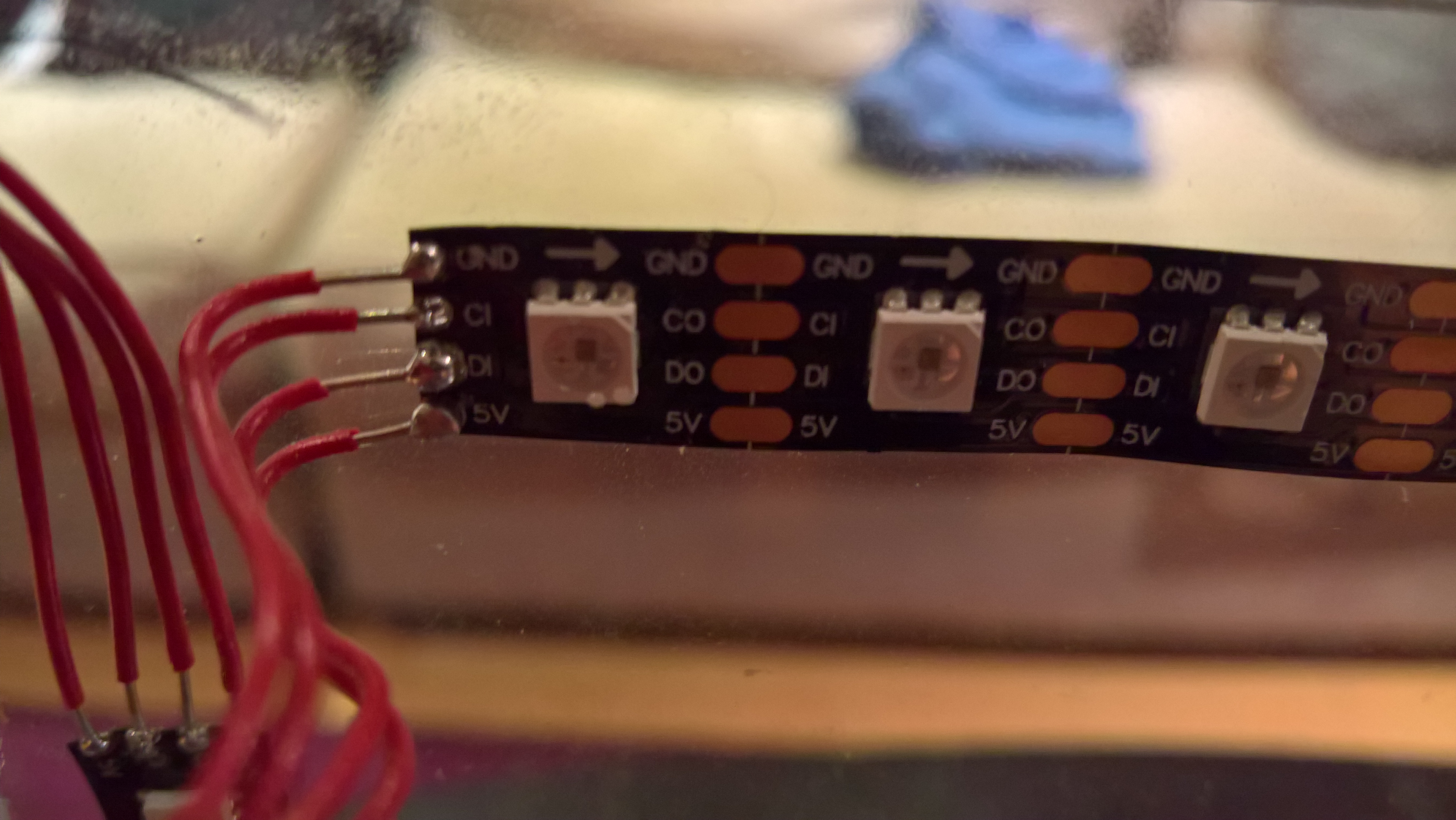
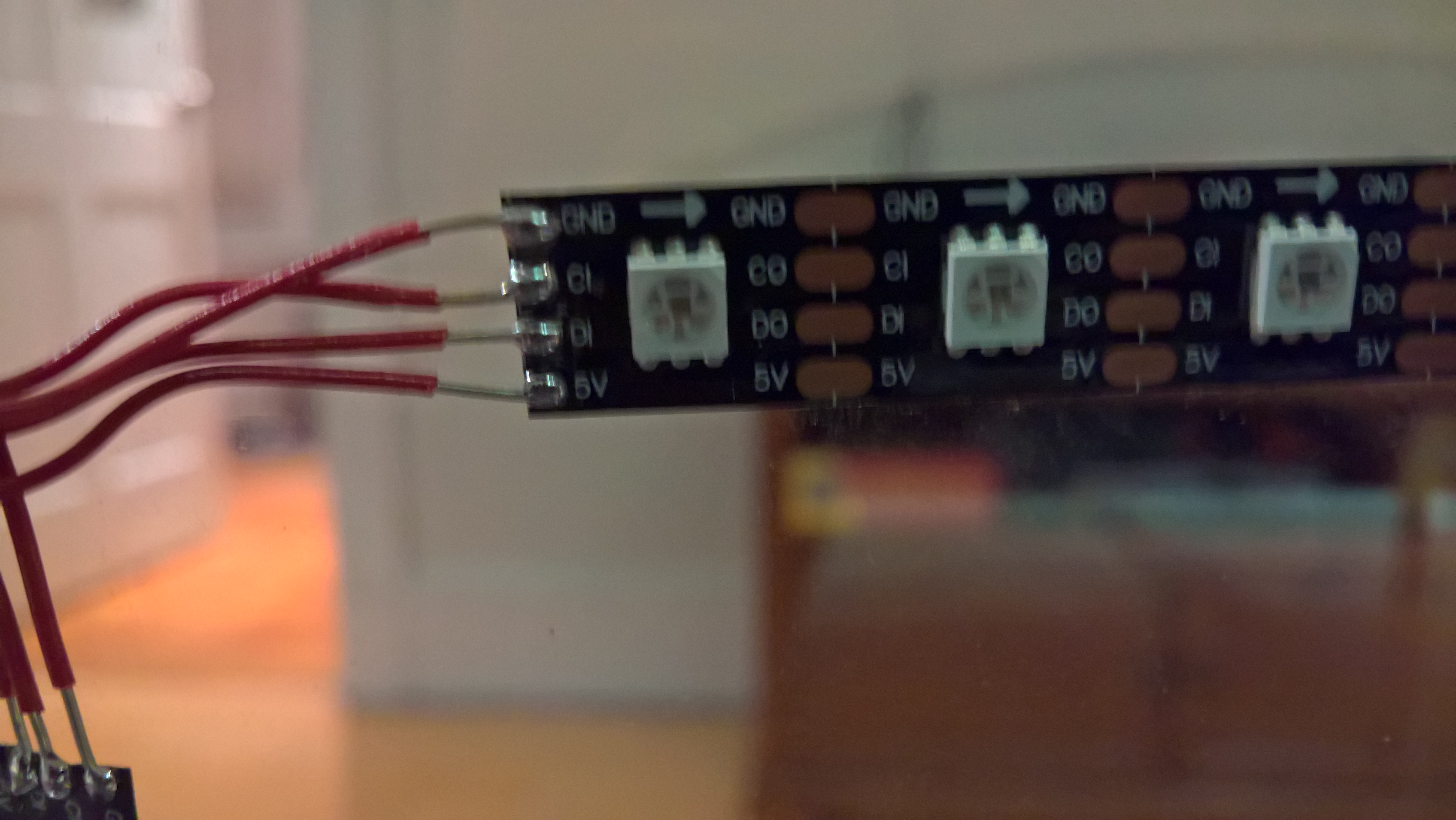
First I needed to set up Windows 10 IoT on the Raspberry Pi. I pretty much just followed the directions on this site. Next I tested actually lighting up the LEDs. My roommate had a box of "maker junk" (wires, wire cutters, breadboards, diodes, etc.) laying around so I wired a LED strip to a breadboard and then wired that to the Raspberry Pi. I also needed to buy a bunch of wires (male to male, male to female, female to female - http://a.co/3vpXVjm). APA102s have 4 input/output wires, power, data, clock, and ground (they also had a positive and negative wire).
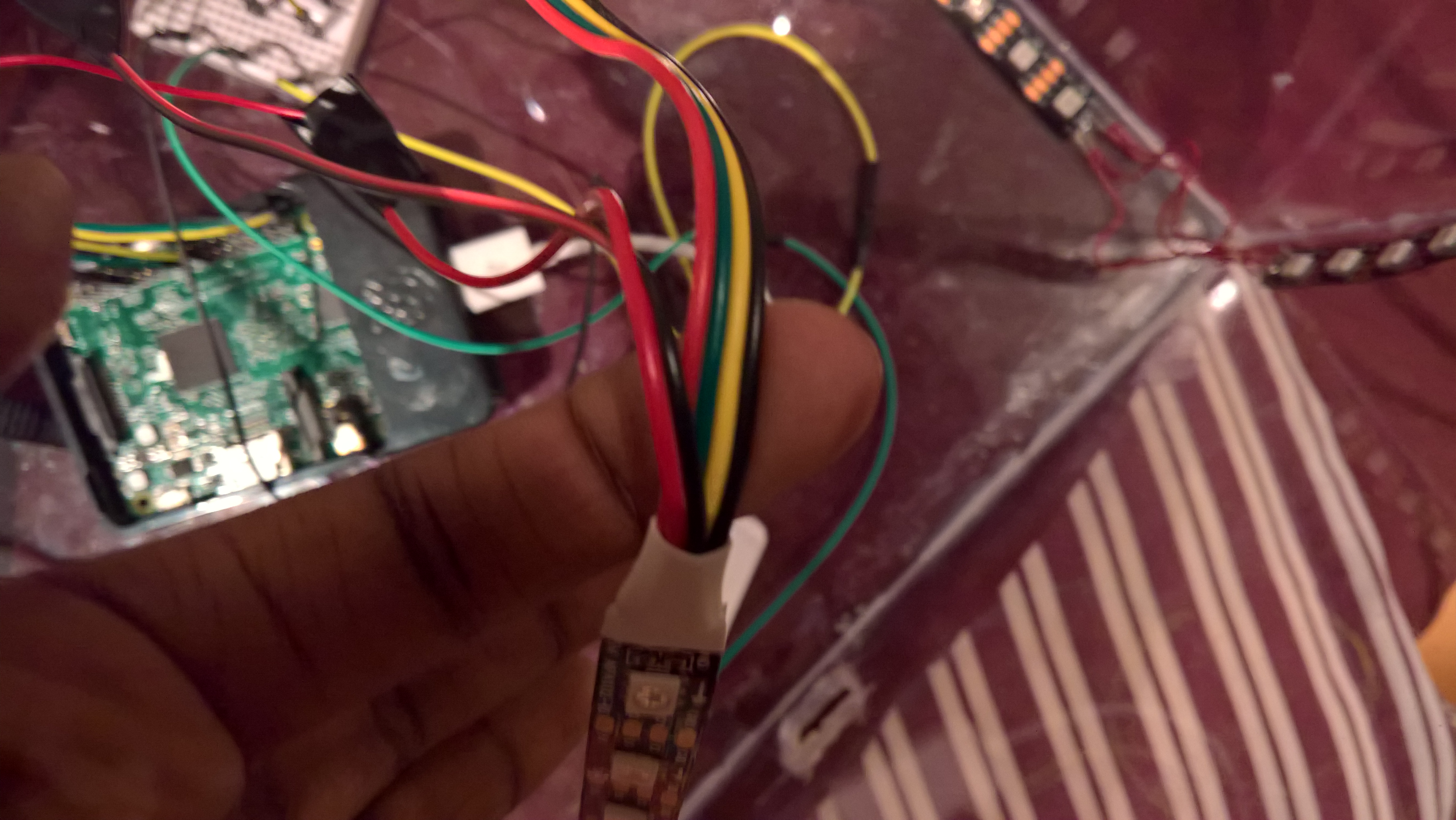
The left red and black wires are the power wires I used. The red and black wires on the 4 wire strip are power and ground for the LEDs
It also helps to color code things so I did: power (red), data (green), clock (yellow), and ground (black). Those then need to hook up to the appropriate pins on the Raspberry Pi. The main power (positive) and negative wire I hooked up to the DC adaptor with the capacitor (I'm still not sure if my capacitor is hooked up correctly, negative to negative???).

The above photo shows the pin layout. Since I was going to power the LEDs from an external power source I didn't need to connect the LED power wire to anything. The data (green) wire I connected to pin 19 which is SPI0 MOSI (master output, slave input). SPI stands for Serial Peripheral Interface. The clock (yellow) wire I connected to pin 23 which is SPI0 SCLK (serial clock). The ground wire I connected to pin 9 which is a ground pin. You may also notice that the SPI labels are labeled under "alternate function". I didn't need to do anything special regarding that to get the LEDs working so I pretty much ignored that.
With everything wired up I needed to actually light the LED strip. This and this post along with the APA102 data sheet was helpful but I also found some sample C# code on GitHub for Windows 10 IoT here.

You first need to send 4 bytes of 0s which is the start frame. Then for each LED you send 4 bytes. The first byte starts with 3 1s then 5 bits for brightness. There are 32 steps of brightness, 0 to 31. The second through fourth bytes are for blue, green, and red respectively. The second post I linked about the APA102s explains how the end frame works. You need at least n / 2 bits of either 0 or 1 (the post says you need 1s but 0s work as well) where n is the number of LEDs in the string. Reading through my code now I noticed I was using n / 2 bytes instead of bits...oh well.
After setting up a few more SPI things (like specifying you're using SPI0) and finding a nice rainbow array online, the LEDs were working!
The Audio (Again)
Next I needed to process audio coming in to the Raspberry Pi. Initially I only wanted to get simple audio detection working. Working with frequencies (which requires a FFT) would come later. To work with audio I needed to use the AudioGraph API. It was pretty complicated at first but after I read through that article a couple times (and found some helpful links) I got something working.
Note that the last two videos were taken July 8th and July 13th respectively. The next video of a assembled box will be much later.
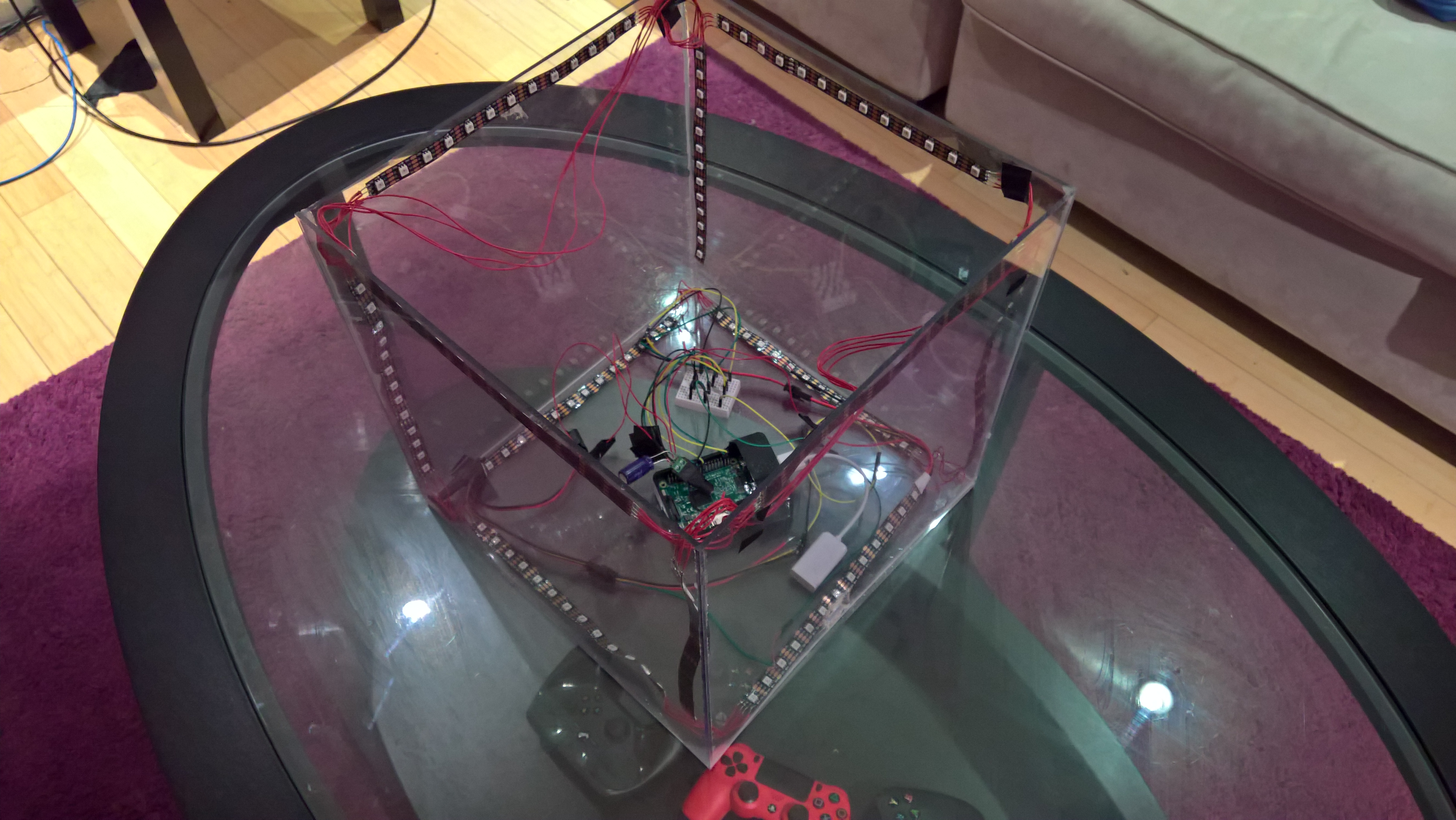
The Build (For Real)
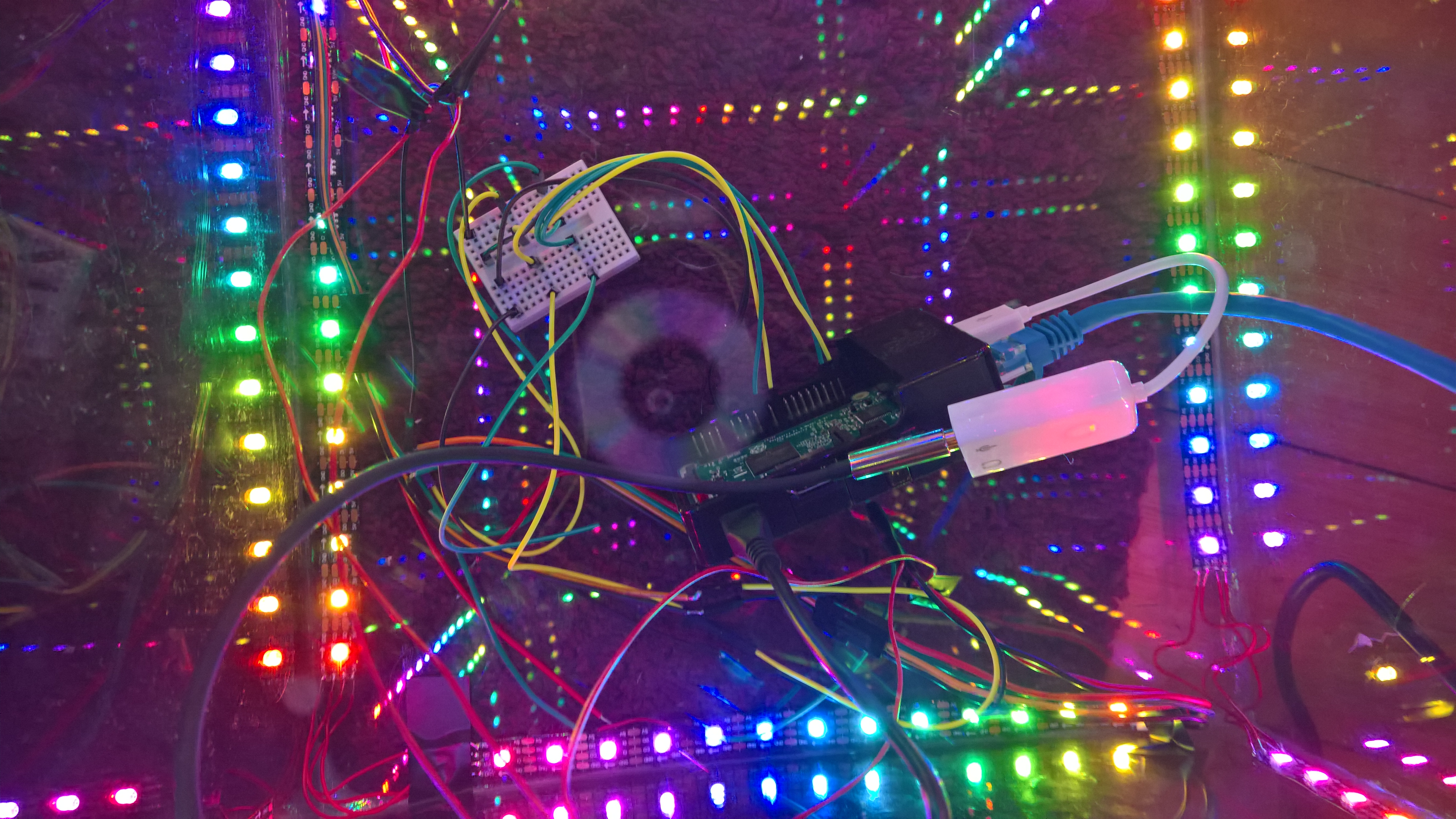
Now that I had some idea of how the box would work it was time to put the box together. I imagined that each edge of the box would have LEDs on it. This was the (very rough) layout of the LEDs.
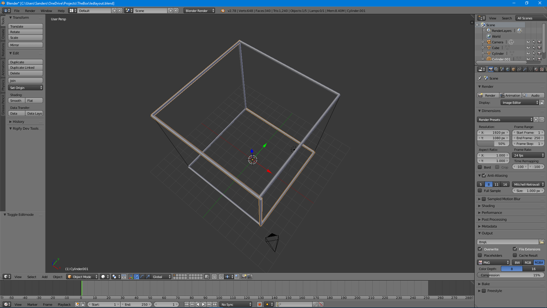
The orange highlighted cylinders represent one connected strip of LEDs
I had initially bought some connectors (from Adafruit) that I thought I could use but they didn't fit with the LED strips so I had to buy a soldering kit and solder everything together. In the end I think I did a pretty good job for it being my first time.
One soldered strip was six individual strips of 13 LEDs each. In the layout picture you may also notice that two edges weren't covered. At the end of one strip the last strip would bridge across one edge to finish the last edge. After a bunch of soldering later the box was assembled!
*I took way too many vertical videos.* *This video was taken September 23rd. Yeah.*(Back to) The Code
The FFT
Getting frequency data instead of amplitude data was the last major hurdle to getting the box fully realized. A FFT can be used to convert amplitude data to frequency data when working with audio. It can also do a bunch of other stuff and involves math so I didn't bother in actually learning how it works. So I found code that computed a FFT, then I found faster code that computed a FFT.
The Visualization
The last step was creating a mapping between frequency data and LEDs on the box. I decided to isolate low, mid, and high frequencies. The low frequencies are displayed by the bottom strips, the mid frequencies on the middle strips, and the high frequencies on the top strips. I then made two modes, volume mode and what I named "speed strip" mode. Volume mode takes the average amplitude of the low, mids, and highs, individually and then displays it on the correct section of the box. There is a little fudging of the averages so that the highs light up as much of the box as the lows since the amplitude of the lows is usually larger than the amplitude of the highs. "Speed strip" mode once again takes in the average amplitude of the low, mids, and highs but instead those values are used to move through a list of colors. The higher the amplitude of a section, the faster the strip will move through the list of colors. These numbers are not adjusted so the low section typically moves faster than the mid and high sections.
When music is playing, the box switches to a random mode every 15 seconds. When the box doesn't detect music it switches into idle mode which either loops through a rainbow on each strip or sends a LED pulse down a random strip every couple seconds.
The Good
That's pretty much it. I pushed the final build of the box on October 21st. And then after working with the LEDs without issue for ~4 months one of the strips shorted out. I think. I think it shorted out because there are some exposed wires that touched something they shouldn't have touched. That's not part of the good. Going with a Microsoft stack had some benefits. I'm very familiar with C# and Visual Studio. Pushing code to the Raspberry Pi was easy. I would hook up the Raspberry Pi to my router using Ethernet, then Visual Studio running on my laptop would find the IP of the Raspberry Pi, then would build, deploy, and allow me to debug code running on the Raspberry Pi. Since the app was also a Universal Windows 10 app I did some of the very early audio tests with the audio card on my PC without dealing with the Raspberry Pi. The box also has a very simple UI that can be used to control it. Microsoft provides an app that lets you see and interact with what the Raspberry Pi is outputting to video. The UI lets you choose what mode the box is in. Whether to auto-cycle through modes, and change the brightness of the LEDs. There was one bug where after switching out of auto-cycle mode on the UI the UI stopped accepting input so I didn't really use it much.
The Bad
I replaced the shorted out strip and then the replaced strip shorted out (I think) as well. I still haven't fixed it. So clearly I'm not that good at electronics. Sometimes Visual Studio ran into issues when deploying so it would just hang and I had no idea how to fix them. A FFT function requires the number of samples you get to be a power of two. The AudioGraph API said that you could choose the number of samples you would get per channel but I always ended up getting 440 samples. Because of this I padded the samples array with 0s to reach 512 "samples" then ran the FFT on that. I also ran into some latency issues when trying to update LEDs when I was outputting debug statements. I think this was because debug statements needed to print to my laptop which meant that the network became involved which is super slow (compared to the CPU). Soldering kind of sucks (I didn't burn myself however) and the box is kind of messy so I do wish that the box was more visually pleasing.
The End
This was my first hardware project so I'm pretty happy with what I made but it could be better. Maybe at some point I'll fix the box again (I may need to buy more LEDs) but I've already started thinking about the box 2.0. I'm pretty happy with the tech stack so that would stay the same. I would like the box to be cleaner, less visible wires, maybe use 120 or 144 LED per meter strips, actually put the strips on the edges, make it so that I can take the cube apart again if needed. All of these changes are on the hardware side, something I improvised the entire time.
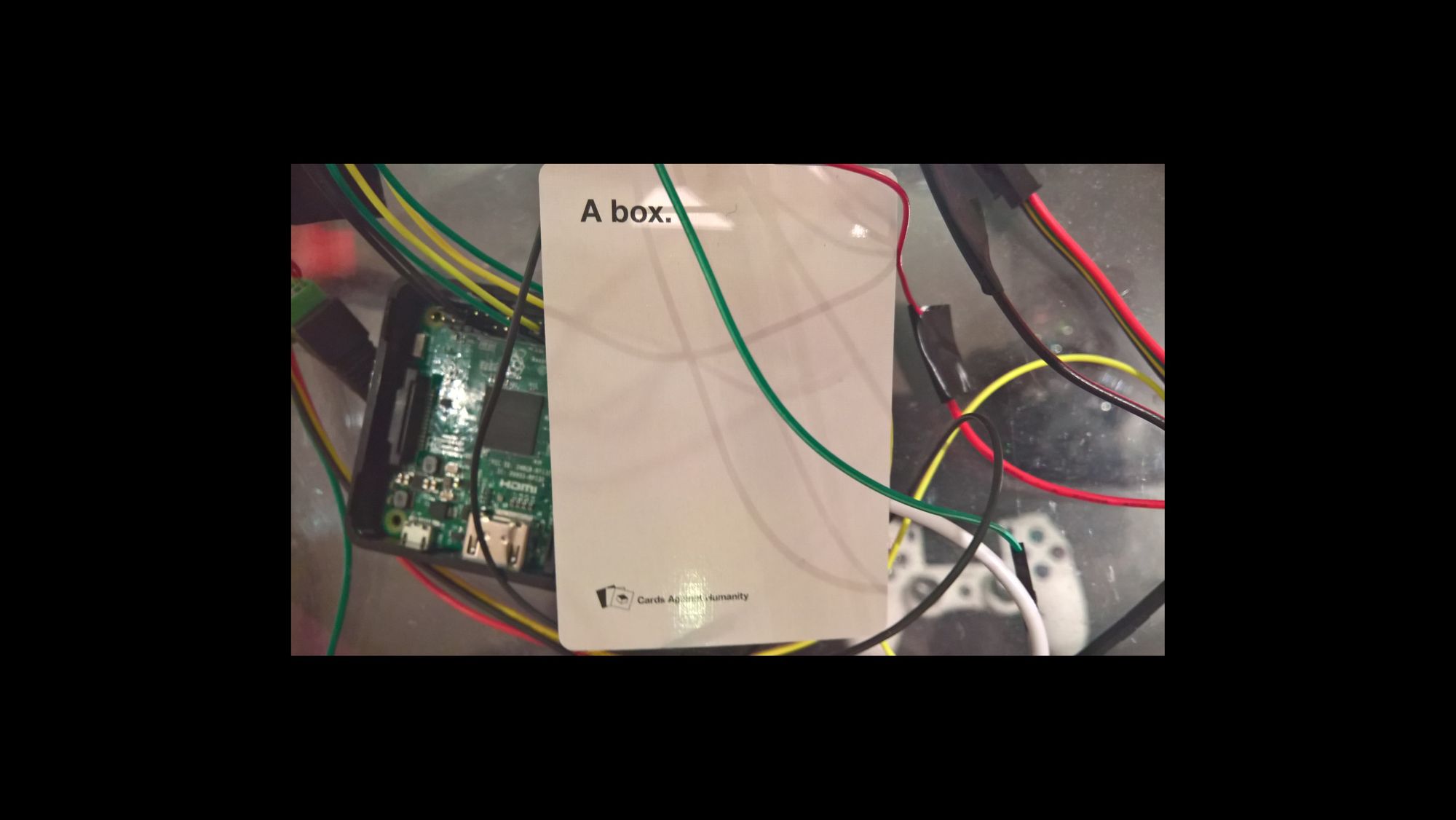
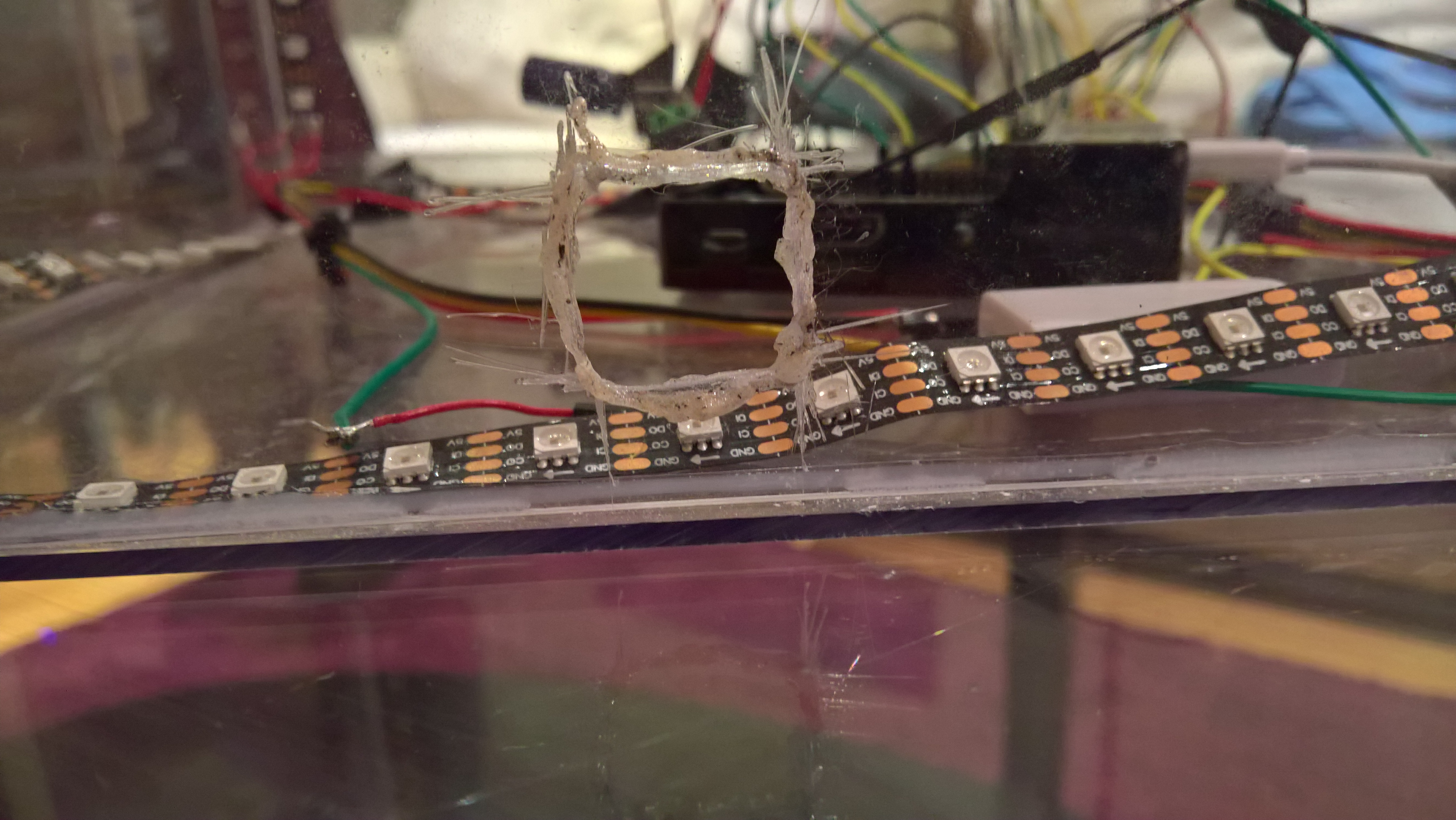
The More
More pictures of the box.
The Other
Here are some other resources that I found but didn't end up using because I wouldn't be able to use them with Windows 10 IoT or the Raspberry Pi
FastLED - LED library for Arduino
APA102_Pi - Raspberry Pi Python library for APA102 LED strips
GPU_FFT - C library that uses the Rapsberry Pi's GPU to calculate FFTs
More explanations on FFTs